In the last post, we explored the second layer of the OSI framework. As we saw, data packets are part of this layer and are encoded and decoded into bits. You can do this with supportive tools that you can categorize as sublayers of layer two: a MAC address and a Logic Link Controller.
The MAC part of this sublayer controls a computer on a network and grants access to data, and it also manages permissions to transmit the data. The LLC part of the layer 2 sublayer controls the synchronization of frames and the data flow and is responsible for error checking. Both tools reside inside a Network Interface Controller (NIC). The NIC is active on layer 1 and layer 2 of the OSI framework.
In this post, we move to the third layer of the model. The third layer provides the missing ingredient of your local connection to networks that are not locally (WANs): routers.
Routing
To interconnect individual LANs into WANs, you need a unique piece of hardware: a router. A router forwards data packets based on their destination IP address. The internet scientists labeled the two connections “WAN” and “LAN.” WAN and LAN provide connection points to the Internet Service Provider (ISP) and a local network. A router reads the IP addresses of the data packets and then determines where it has to send these packets.
A simple home router serves multiple functions. It is often a combination of a router, switch, Wi-Fi WAP (Wireless Application Protocol), DHCP (Dynamic Host Configuration Protocol: auto connecting a device to the network), and a firewall. A home router with all these functionalities operates on more than one OSI model layer, but the router part is on layer 3.
Routing Tables
When a data packet enters a router, the router strips off all the Layer 2 information and puts the “naked” IP packet in a queue. After this, the router inspects the destination IP address of the packet and sends the IP packet to the correct port. You do this with the support of a routing table. This table tells a router to which destination it has to send the packets. To thoroughly understand the process of packet management by the router, a complete understanding of this routing table is required. Shortly: without a routing table, a router can’t do anything. The below picture shows a routing table. You get this table by typing the #routing command in Linux, and in Windows, you can get an overview almost the same as the command “route print.”
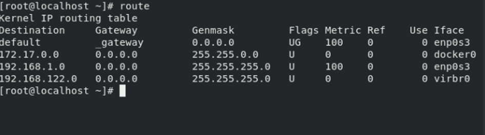
Understanding this table is vital to be able to understand the routing table. Below is a brief description/summary of the different columns.
Destination
The destination is the defined network. A router lists all directly connected network IDs in this table to one of the router’s ports.
Gateway
The Gateway column shows the IP address for the “next hop” router. The router makes brief stops (hops) at other routers that forward the packet to the next router in the network until the data packet reaches its final destination. In case a network ID is not directly connected to a router, the Gateway column instructs the router to which IP address of a destination router it sends the packet. That destination router handles the data packet, and your router completes its job with this action. You don’t need a gateway if a network ID is directly attached to the router. When no Gateway is required, most routing tables put 0.0.0.0 or “On-link” in this column.
Genmask
A subnet mask is mandatory to define a network ID. The router names a subnet mask “Genmask.” You use a subnet mask when you have more than one IP address (read: device) attached to a network. With a Local Area Network (LAN), this is always the case. A Genmaks uses “0” in the address as the network address or network identification and the “255” address as a broadcast address. You can’t assign both addresses to a host.
Flags
A flag describes the destination of a data packet. The “U” means the route is up and working as intended. If you look to the “H,” you should know that this is a host of the route: a complete IP address for a system on the network and not a subnet. The “G” means that the route is to a gateway.
Metric
A metric shows the associated cost of using the indicated route. It shows the minimum number of “hops” (the routers a data packet has to cross) to the network ID. A metric is a vital part of the routing table. Let’s take an analogy. There are more options if you want to get from city A to city B by car. Usually, you choose, for instance, a highway that directly connects city A to city B. But if the route is closed because of repairs, you have other options. The same is the case with routers. Usually, a router automatically chooses the most efficient path from starting point to the end destination. A network engineer can assign a different metric for each route. Network engineers do this with dynamic routing protocols. The route with the lowest metric always “wins.” It would be best if you were very careful with these setups. They are susceptible to mistakes, and making a mistake can result in no connection at all—my advice: always leave this to the pros and don’t try to do it yourself.
Ref
The ref shows how many references there are for a specific route. It tells you how many other routes (gateways crossed) rely on the presence of this route.
Iface
The router has to use specific ports. The Iface column gives these instructions to the router. The descriptions in this column vary depending on your operating system (OS). We used Linux in this example, and Linux shows names for interfaces like eth0 and bro0, and other Operating Systems use different terms like Gig0/0 or Gig0/1, etc.
The router uses the combination of the destination and subnet mask (genmasks) to check if a packet matches a specific route.
Network Address Translation (NAT)
Looking to the future, we need to consider that IPv4 will run out of addresses. You can still get an IP address from an Internet Service Provider (ISP). Still, it’s much harder to get these. Routers that run a Network Address Translation (NAT) hide the IP addresses of computers on the LAN but still grant these computers the ability to communicate with the Internet. NAT saved the useful life of IPv4. Do not confuse NAT with routing: it is something completely different.
A NAT replaces the source IP address of a computer with the source IP address from the outside router interface on packets that leave the local network. Not all routers can handle NAT: you need a particular type of router that can take Network Address Translations. If you want this functionality, check if the router you purchase has the NAT feature.
Essential tips when handling routers
Never plug a brand new router into an existing network. You don’t know what a router is going to do. For instance, if it has a DHCP, you might automatically create a rogue DHCP on your server. Check if there are routes on a router that match up to other network addresses as well. If this is the case, data packets disappear in the sky. To prevent this, configure a router before you put it online and leave it to the network pros. Most network engineers use a laptop and a crossover cable to connect to a new router. They move to the Web interface first, setting a static address for the computer to place a desktop on the same network ID as the router.
When you have set up everything correctly, you must always enter a default username and password. This username and password come with the documentation of the router. Always change the default name and password to harden your network. Default usernames and passwords are also available to third parties, and you don’t want to give these parties an easy time logging onto your router.
With a growing network with many routers, administrators need more advanced tools that describe, visualize, and configure the entire network—Use Network Management Software (NMS) for this. NMS can centrally communicate to all network routers, switches, and even computers, giving you an overall view of your complete network.
Final Thoughts
Layer 3 is the gateway to a Wide Area Network (WAN), and the Internet is the biggest of all WANs. This layer is home to switching and routing technologies and is also home to creating logical paths (virtual circuits) that transmit the data from node to node and is also part of this layer. A node inside a network is a device or data point part of a more extensive network. For instance, computers, telephones, and printers are all examples of a node.
To direct data packets to other networks, you need a navigation system that handles a package from one destination to another. It is comparable to a navigation system in a car, and this network navigation system is called a “Router.”
Feel free to contact me if you have questions or in case you have any additional advice/tips about this subject. If you want to keep in the loop if I upload a new post, do not forget to subscribe to receive a notification by email.