In my previous post, we started the journey through networking by following the OSI framework. With this framework, you get a clear overview of how you set up a network correctly. It also gives you a solid troubleshooting guideline in case of problems in your (organization’s) network.
After discussing the OSI model’s basic concept and explaining how the bottom layer, the Physical Layer, works, this layer represents the network at the electrical and mechanical levels. The hardware in this layer sends and receives data on the carrier: cables, cards, and other physical aspects. Examples of this layer are hubs, repeaters, and cables. After this brief recap, it is time to dive deeper into the following layers of the model. Here we go!
The Ethernet
In 1973, Xerox developed networking technology that was named Ethernet. Xerox built Ethernet on a bus topology. In a bus topology, you connect every computer on a network to the same cable: the bus. The bus topology was one of the first network architectures. This type of architecture has been obsolete for many years with the introduction of more modern network topologies in the 90s that use a hybrid star-bus topology. After a few years of internal use, Xerox decided in 1979 to share this technology with the outside world by looking for partners to make Ethernet an industry standard.
Together with Digital Equipment Corporation (DEC) and Intel, Xerox published the first ethernet standard, DIX (Digital/Intel/Xerox). After they developed this standard, they transferred control of this Ethernet standard to a neutral party: this neutral party is the Institute of Electrical and Electronics Engineers (IEEE). The IEEE created the 802.3 (Ethernet) working group to control the Ethernet standard, which is still the case.
What the DIX collaboration did was very special. By transferring control to IEEE, Ethernet became open source and enabled anyone to make interchangeable equipment for Ethernet.
The Ethernet designers had the same challenges that any network architect has. They needed to find a way to send all the data across the wires, identify the devices sending and receiving all the data, how they should use the cables, and share at what time. These brilliant people invented Media Access Control (MAC) addresses to solve one of the missing pieces of this complex network puzzle.
Media Access Control (MAC) addresses
If you send a letter to someone, you need an address. Otherwise, the person you want to send the letter to will not receive this letter. Additionally, this person would also like to know who the sender is to check if the letter received was meant for them. This verification process is done by assigning the letter to a sending and receiving address.
Networks have similar challenges as mail has, but the solutions are slightly different because the anonymity of networks is more significant than mail traffic by physical mail between two persons. If you want to remove anonymity, identification is required, and you need to identify the devices sending all the data over the network.
The human world invented Social Security numbers to identify people, so it makes sense that devices can use the same concept. Network scientists had the same idea and used the image of unique identification numbers for computers, and they named this identification number a Media Access Control (MAC) address. With this Social Security number for computers, you can identify these computers on the network and identify the sending and receiving devices and data packages.
A MAC address is part of the Network Interface Card/Network Interface Controller (NIC). Every card has a ROM chip burned onto its circuit board, and this is special firmware and contains a unique, 48-bit identifier.
MAC is part of OSI layer 2, while the physical NIC card is OSI layer 1, making NIC a hybrid device that operates in both layer 1 and layer 2.
Ethernet Frames
Another challenge was sending all the data across the wires. The network scientist did this by creating frames. The computer breaks transmitted data into segments (datagrams) and places these segments into packets. After this, the computer transforms these packets into frames.
Network scientists solved two networking issues by using frames. It prevented a single machine from claiming all capacity of the shared bus cable. In addition, by using brackets, retransmitting lost data became more efficient. Retransmitting lost data is accessible in small frames because a computer only has to retransmit the damaged frames. Imagine that a full container has to be retransmitted in total over the network again. Not very efficient, and it would take a lot of capacity.
A computer splits a frame in a preamble, an SFD, and the Ethernet frame structure. You can break the Ethernet frame structure into five separate pieces, and if you add up everything, you have seven pieces in total for a full frame:
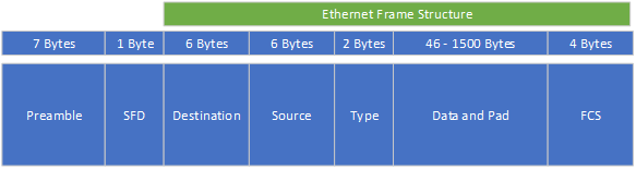
Piece 1: The preamble
A preamble gives a receiving Network Interface Card/Network Interface Controller (NIC) time to prepare for an incoming frame and to know where the frame starts. The NIC adds the preamble to a frame.
Piece 2: the Start Frame Delimiter (SFD)
The SFD is an eight-bit (one-byte) value and marks the preamble’s end. The Start Frame Delimiter is the first field of an Ethernet packet, indicating the start of an Ethernet frame.
Piece 3 is the destination address (Ethernet piece 1)
Ethernet frame piece 1 is the destination address: the MAC address of the receiving system.
Piece 4 is the source address (Ethernet piece 2)
Ethernet frame piece 2 is the source address: the MAC address of the sending system.
Piece 5 the type of data sent (Ethernet piece 3)
Ethernet frame piece 3 is the type of data. This piece helps the receiving system to interpret the frame contents on a fundamental level. For instance, it tells the receiving system if the frame contains IPv4 or IPv6 data.
Piece 6: the data itself (Ethernet piece 4)
This piece contains the entire “payload” a frame carries. Payload is the capacity a packet has. For instance, if a frame holds an Internet Protocol (IP), the package will include information like the source and destination of systems, and IP addresses initialize this.
Piece 7 The Frame Check Sequence (Ethernet piece 5)
Ethernet frame piece 5, the Frame Check Sequence (FCS), does a “health check” on the data. The frame checks for damaged data during transit. They have a unique code to do this. The code runs data through a mathematical formula called cyclic redundancy check (CRC). This calculation results from the FCS attached to the frame as the “trailer.” When the receiving system opens the frame, it performs the same calculation and compares the calculation answers with the ones included in the frame. If the answers do not match, the receiving machine drops the frame.
Transmitting frames with the Logic Link Control (LLC)
Systems split data into frames, but data also need to move. In addition to the MAC functionality managed by the Network Interface Card/Network Interface Controller (NIC), a NIC also manages the flow of the data frames. The Logic Link Control does this (LLC). The LLC is the part of the NIC that communicates with the system’s operating system. Usually, device drivers take care of this process.
Logic Link Control places the outbound data from the upper layers in the OSI model: the software, into frames and creates the Frame Check Sequence (FCS) on each of these frames. The LLC also manages incoming frames, and it processes the frames addressed to the NIC and deletes the frames addressed to other machines on the network.
Like the MAC functionality, it proves that a NIC operates on both Layer 1 and Layer 2 of the OSI model. The physical side, the NIC device itself, is working on Layer 1. Frames also move into and out of the cables plugged into the NIC, making it part of Layer 2: Data Link.
Summary
Summarized, at Layer 2, the data packets are encoded and decoded into bits. Encoding and decoding are required because a computer doesn’t speak the human language. You need to translate data into binary language because of this. Otherwise, you can’t transport all the data on the network. Knowledge about transmission protocols (TP) and how to manage these protocols properly is required.
Layer 2 also supports solving errors in the physical layer like flow control and data synchronization. You can divide the Data Link Layer into two sublayers: the Media Access Control (MAC) layer and the Logical Link Control (LLC) layer.
The MAC part of the layer controls a computer on a network to access the data and manages permissions to transmit the data.
The LLC part of the layer is responsible for controlling the frames’ synchronization, controlling the data flow, and doing error checking.
Final Thoughts
We take the Internet for granted, but there is an entire hidden world behind all this. Most people do not realize this because the sending and receiving of data are not visible to them. Cables are hidden and binary traffic through these cables as well.
We should not forget how impressive it is how a group of great minds tinkered with the whole architecture and concept of networking. Seven World Wonders are defined: the Great Pyramid of Giza, the Colossus of Rhodes, the Hanging Gardens of Babylon, The Lighthouse of Alexandria, The Mausoleum at Halicarnassus, the Statue of Zeus at Olympia, and the Temple of Artemis. In my opinion, Ethernet/the Internet should be part of this list. We should not forget that the Internet might be the greatest accomplishment of all time, unifying vast groups of people and allowing people in less privileged positions to learn and receive knowledge available to them without the Internet.
Feel free to contact me if you have questions or in case you have any additional advice/tips about this subject. If you want to keep in the loop if I upload a new post, do not forget to subscribe to receive a notification by email.