When you encounter complex technologies, you need to simplify the process by breaking it down into simple, isolated processes and actions. This is done by using a network model. Practice is important but without a guideline/roadmap you might get stuck or come up with a solution that is not the most optimal one.
Frameworks guide you in structured troubleshooting as well. This is efficient and leads (in most cases) to the biggest satisfaction of the organizations and users you are helping out
A network framework relies primarily on Open Systems Interconnection. This is a seven-layer model, also called “OSI”. In this series of posts, I will introduce you to the OSI model and the different sets of layers. So buckle up and hope you enjoy the ride.
This first post about the OSI model will focus on the basic concept of this model, a brief introduction of the 7 OSI layers, and a detailed analysis of the first layer of the OSI model, the Physical Layer: the Hardware.
The OSI model – Basic Concept
As said in the introduction, it is important for networking engineers to have a tool that guides them through the (sometimes literal) forest of cables and connections. This is the reason why The International Organization for Standardization (ISO) created the OSI seven-layer model.
The OSI model gives networking engineers a mental tool that helps them to diagnose problems. The more experienced an engineer becomes, the more this model will be used subconsciously.
By understanding the OSI model clearly, an engineer can quickly determine at what layer a problem occurs. This helps the engineer to zero in on a solution without wasting a lot of time on false leads/false positives.
In addition to this, the OSI model creates a common language that helps engineers to describe specific network functions. The world of IT is inundated with legions of terms and abbreviations. Unclarity, confusion, and mistakes in the communication between two or more engineers can happen more easily if there is no clear guideline/framework that keeps engineers on the same page.
Setting up a framework like this is called “Philosopher translator Secratory Architecture”. This type of architecture is based on a situation in which two philosophers (A+B) are in different locations, not knowing the same language. However, they want to send a message. This is a challenge but can be solved by taking some basic steps:
- Philosopher A passes the message to someone in his/her network that can translate the message into a common language that can be understood by someone in philosopher B’s location that is in his/her network.
- Then the converted message will be sent from Location A to Location B. At location B, the person in philosopher B’s network will understand the message and will pass it to philosopher B in the language that philosopher B understands.
Communication in the OSI Model works the same way. Each layer has different protocols that need to be followed for the successful transmission of a message between network engineers.
The OSI Layers
Every layer in the OSI-layer model defines an important function in computer networking. The protocols that operate at that layer offer solutions for these functions. A protocol is a set of clearly defined rules, regulations, standards, and procedures that enable developers of both hardware and software to make devices (hardware) and applications (software) that operate properly at a particular layer in the OSI model. There is full trust between those layers because no organization will suddenly deviate from the set layers. It would create hardware and/or applications that would not operate in the right way with the rest of the network layers.
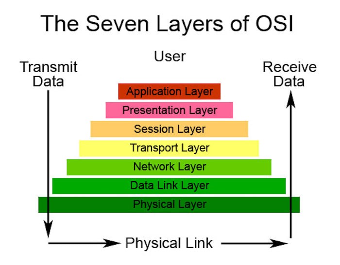
The OSI model is divided into two groups. One group is responsible for the “Host” which has 4 layers and the other group is responsible for the “Network” which has 3 layers. In total there are 7 layers:
- Layer 1: the Physical Layer (Network)
- Layer 2: Data Link Layer (Network)
- Layer 3: Network Layer (Network)
- Layer 4: Transport Layer (Host)
- Layer 5: Session Layer (Host)
- Layer 6: Presentation Layer (Host)
- Layer 7: Application Layer (Host)
In general, the model structure is set up the other way around. It starts with layer seven and ends with layer 1. You can see it as a pyramid: you start with a foundation, and all after the first layer are dependent on the layers below. If you would remove one of those layers, the model would crash down and the specific layer can’t be used. For example, if you have an Application Layer and you remove the Physical Layer you can’t use the Application Layer anymore.
I’ll start with layer one of the model instead of layer 7. Sometimes layer 7 is explained first but to me, this is a bit confusing.
Layer 1 | Cabling
All networks are connected in some way with cables. Looking to a classic network inside an organization (ethernet), this is done by cables that are named unshielded twisted pair (UTP). A UTP cable usually has four pairs of wires that can send and receive data.
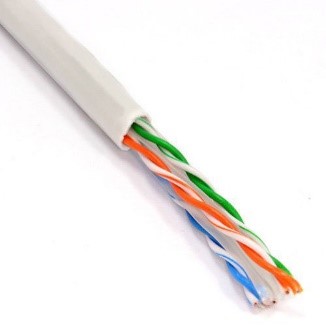
Every type of hardware that moves data from one system to another (copper cabling, fiber optics, but also radio waves), is part of OSI layer 1. For layer 1 it doesn’t matter what data does. It is only important for layer 1 that data is moved from one system to another.
In most cases, cables are also the first visible components that hint at a physical network but there are more types of hardware required to be able to communicate.
Layer 1 | Network Interface Card: NIC
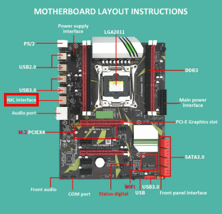
When you plug a cable into a computer, you do this by inserting it into a special socket. This socket is part of the Network Interface Card, also called (NIC). This card is the interface between a PC and the network. Older computers use the NIC as a separate card that is plugged in an expansion slot inside the PC. This is why it was called a Network Interface Card.
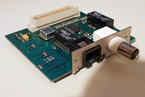
Nowadays, NICs are built inside the motherboard.
Because of the increasing popularity of wireless, network cards with an RJ45 socket (RJ stands for Registered Jack), have been losing popularity as well.
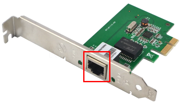
However, even with these technological advancements, NICs are still called NICs. The full name is just tactfully replaced and it has the same abbreviation: Network Interface Controller.
Every NIC has a ROM chip burned onto its circuit board. This is special firmware and contains a unique, 48-bit identifier. This identifier is called a Media Access Control Address, or shortly: a MAC address. There are no two NICs in the world that share the same MAC address.
Every NIC producer needs to contact the Institute of Electrical and Electronics Engineers (IEEE) and request a block of MAC addresses that are then burned into the ROM on the NICs that a producer of NICs makes. MAC addresses are always produced in hex characters. Each hex character represents 4 bits and it takes 12 hex characters in total to get to the 48 bits, previously mentioned.
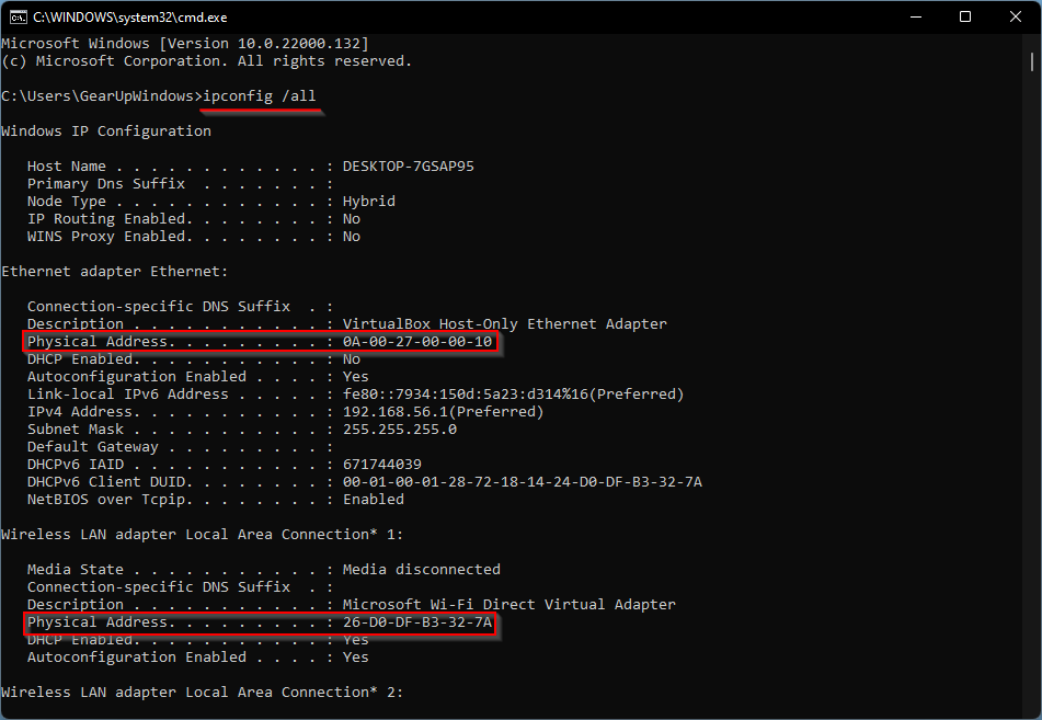
If you want to know your MAC address you can type ipconfig /all from a command prompt of your Windows system:
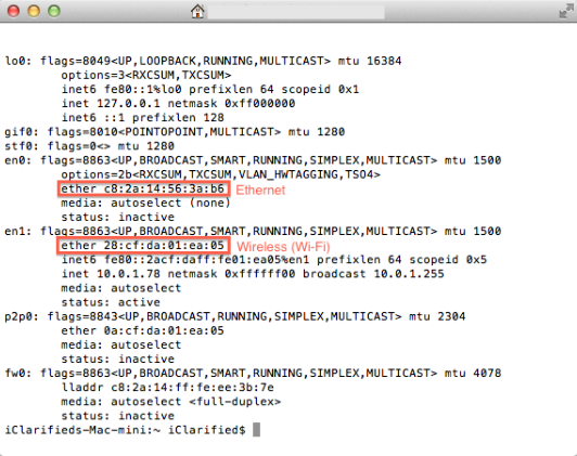
If you use a macOS you do this by typing ifconfig from a terminal:
and in case you use a Linux system, you can type in “ip a” from a terminal:
NICs, send and receive binary data (0s and 1s) as pulses of electricity, light, or radio waves. In this, a charge of electricity is identified as binary “1” and no charge is identified as binary “0”. Summarized, data is translated by a device into binary by charges (1s) and non-charges (0s).
However, you can’t send a continuous stream of data throughout a network. It is broken down into chunks, called frames. A frame is a container with a chunk of data that moves across the network. The frame encapsulates (puts a wrapper around) the binary information that is created by an electronic device. This way, data can be transmitted more easily. The NIC creates, sends, receives, and reads these frames. This makes a NIC an indispensable component of data transmission. Without it, you can’t transmit any data. I will stop talking about data and frames now because this is part of the second layer. We are talking about hardware only now but this piece of information was required to fully understand the working of a NIC.
Layer 1 | The “magic” box that guides the frames
When a system sends information packages (frames) through the network, it needs a guide to lead it to the right receiving system. Without a guide, a frame does not know where to go and keeps traveling. This is done by placing a device in the middle of a network that acts as some sort of traffic officer. It stops incoming traffic and then sends it off to a specific destination.
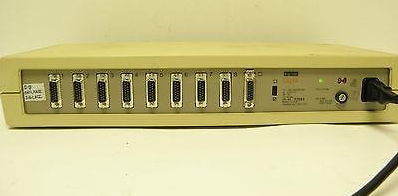
The Hub
When I was introduced to networks at my local computer club in the 90s, network gaming was done by connecting computers with hubs. Hubs were the first “traffic officers” in networking. When a frame was sent from one computer to the other computer it was received by a central hub first. This hub copied the frame and send the copy of the original frame out to all connected ports except the port on which the frame originated. The copy of the frame was received by all the connected systems, but only the NIC to which the frame was addressed, would process the frame. The other NICs dropped the frame when they noticed that it was not addressed to their MAC address. In other words: every NIC received every frame that was sent on a network, but only the NIC with the matching MAC address would process the frame. The rest of the NICs just dropped the frame. Not very efficient and because of all the network activity, it did hurt speed a lot as well.
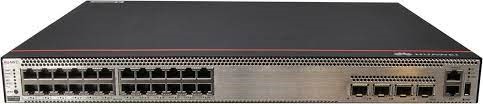
The Switch
To solve this inefficiency issue, networks replaced the hub with a smarter device: a switch. A switch filters traffic by MAC address. Because it can filter MAC addresses, it can send a frame only to the system that is associated with the destination MAC address instead of sending all incoming frames to all network devices it is connected to like the hub. Switches bring much better scalability than hubs which meant that network performance (read speed) increased a lot with the introduction of the switch.
From the outside, a switch looks the same compared to a hub and when you turn on a switch it also acts the same as a hub, passing all incoming frames right back out to all the other ports. However, as it forwards all frames the switch copies the source MAC addresses and quickly creates a table of the MAC addresses of each connected system. This is called a Media Access Control (MAC) address table.
After the table is created, the switch acts as a telephone operator from the past: it creates an on-the-fly connection between the two devices. While both systems communicate with each other, it appears that they are the only two systems on the network (which is hardly the case most of the time).
Each port on a switch is in its collision domain, preventing frames to collide with each other. Additionally, the switch can buffer incoming frames as well. Buffering means that two endpoints (systems) that are connected to the switch, can send data at the same time and the switch will handle this without any collision: a technological wonder!
Final Thoughts
Shortly summarized, the Physical Layer (layer 1) is responsible for the transmission and reception of the unstructured raw bit stream that runs over the physical medium. Key components to do this are cables, switches, and NICs. These components form the basics of your physical infrastructure and without any of the 3, a decent network structure can’t exist. Switches can be excluded and you can set up a direct link between devices by connecting cables directly but that is not a sustainable solution for a stable network that has to be created in an organization.
Feel free to contact me if you have any questions or if you have any additional advice/tips about this subject. If you want to keep in the loop if I upload a new post, do not forget to subscribe to receive a notification by email.


